Tutoriel TSI : démontage du collecteur d’admission sur une Golf 6 Gti 211cv
Le moteur 2.0 TSI EA888 GEN 1, installé entre autre dans la VW GOLF 6 Gti 211cv ou encore dans le VW SCIROCCO 2.0 TSI 200cv est aussi concerné par un encrassement des soupapes d’admission (comme le 2L TFSI EA113 des Golf 5 Gti, Golf 6 R, Audi S3). Voici donc un tutoriel en anglais concernant le démontage complet du collecteur d’admission et du nettoyage du collecteur d’admission et des soupapes.
Comment démonter le collecteur d’admission sur le 2L TSI ? Besoin d’un coup de nettoyage sur les soupapes ?
Source : VWVORTEX.
Overall the removal is pretty easy and straightforward. Just take your time removing and disconnecting everything. Take pics so you can reference during the reinstall. Overall removal time is about 1-2 hours depending on your speed and access to tools. Having the right tools makes it simple.
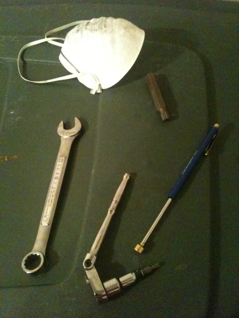
Tools Needed
• Sharpie marker and plastic baggies to store screws / bolts and label where they came from
• 3/8’ inch ratchet with 90* adjustable angled head
• Socket that will hold torx bits
• #10 triple square (12 point)
• T-30 bit for all manifold related screws
• 9” ratchet extensions
• Protective gloves
• Respiratory mask for valve cleaning
• 17mm open wrench
• 10mm socket for disconnecting battery
• Sockets for hose clamps on throttle body, etc.
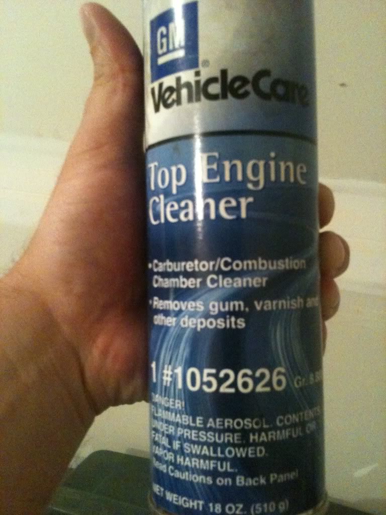
• GM Top Engine Cleaner, Part# 1052626 (aerosol can)
• Shop rags
• Wire brushes (cylinder bottle type)
• Metal pics
• Compressed air
• Vacuum cleaner
• Good ventilation
Manifold Removal
1. Lift front end of car
2. Disconnect fuel pressure sensor on top of fuel pump; turn on car and let idle for 10-15 seconds to lower fuel pressure from pump and rail.
3. Disconnect battery
4. Remove air intake (I have a Carbonio intake; I could have probably kept it on the car but it made it much easier to get to the fuel pump with it off)
5. Remove throttle body pipe
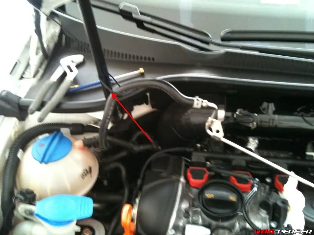
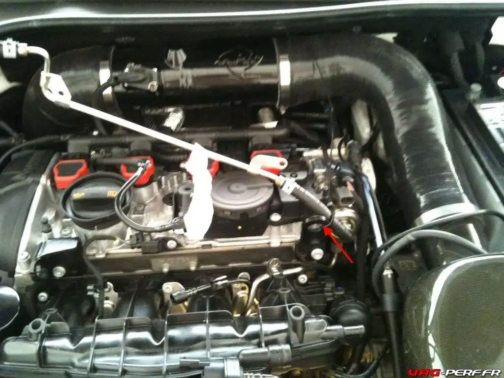
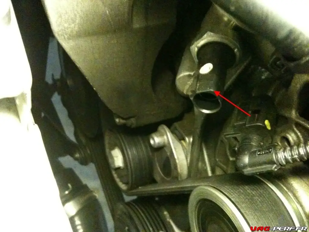
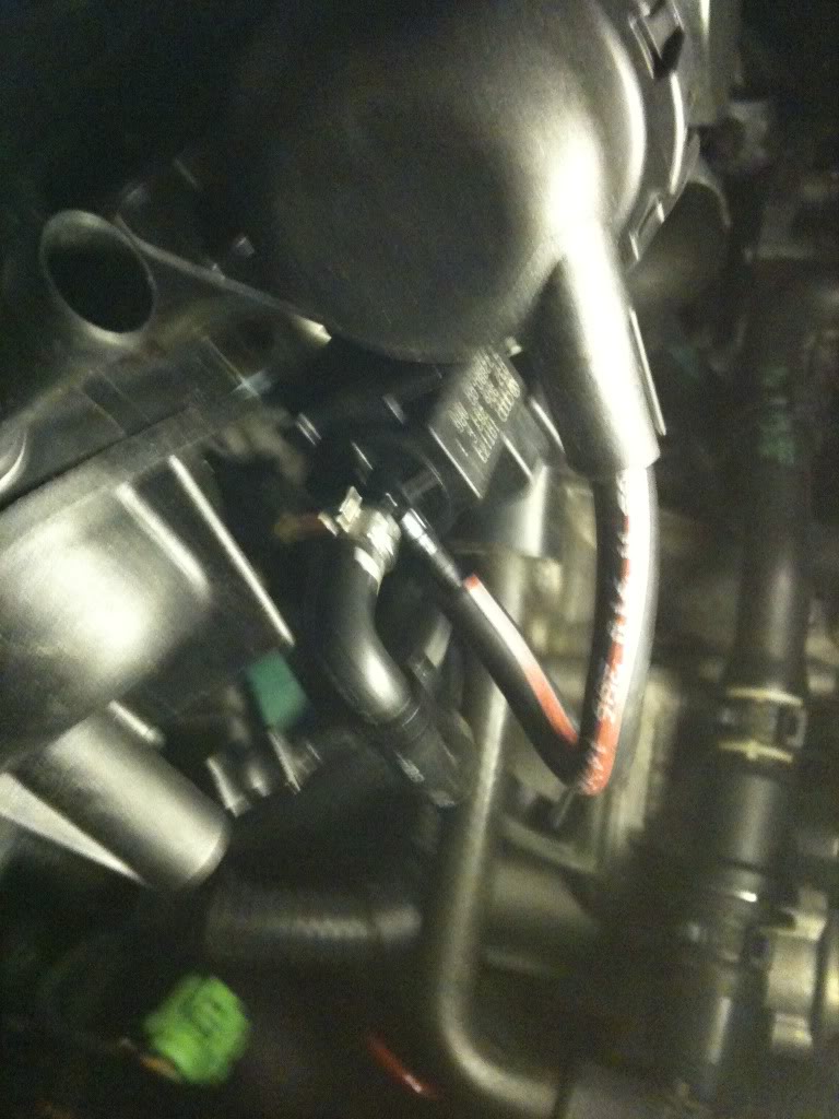
6. Disconnect PCV hose from manifold and PCV assembly on engine.
7. Disconnect sensor located on head beside PCV assembly.
8. Remove the 2 T-30screws that hold down the fuel rail and the 1T-30screw holding EVAP hose on top of mani. Use wire tie to suspend fuel rail out of the way. (I used the hood bracket and engine lift bracket to tie wire-ties around.
9. Remove 1 T-30screw on top of mani that is holding down fuel hard line .
10. Remove 2 T-30screws for wiring harness assembly that connects to the mani on the right side; remove sensors from assembly and take note of their orientation so you can assemble them into the wiring bracket later.
11. Remove 1 T-30screw located left of throttle body that holds the coolant line harness to mani.
12. Remove 1 T-30screw located on far left side of coolant harness (about 6” left of throttle body).
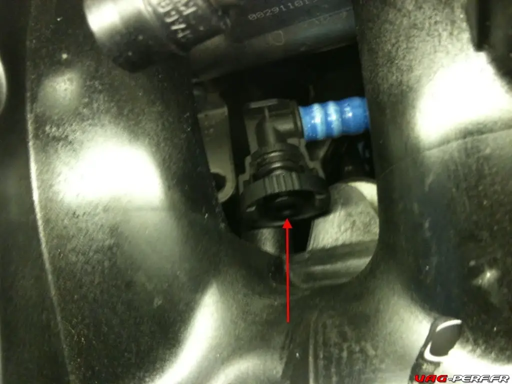
13. Disconnect spring clamp from purge valve and pull purge valve hose from valve. – store hose out of the way.
14. Place rags underneath bolt attaching fuel line to fuel rail assembly under intake mani , disconnect bolt using a 17mm open wrench then disconnect bolt under fuel pump using 17mm wrench. Use caution cause fuel will spill and may be under pressure if step # 2 wasn’t followed correctly. Use eye protection.
15. Disconnect vacuum actuator flapper sensor by sliding off of assembly mounted to mani and remove the vacuum line.
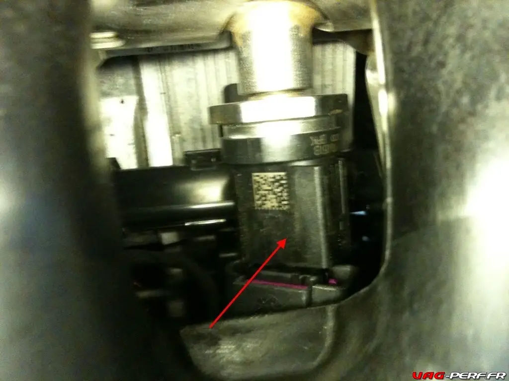
16. Disconnect fuel pressure sensor located underneath 1&2 runners.
17. Remove throttle body sensors.
18. Remove throttle body by unscrewing 4T-30bolts located underneath the throttle body assembly.
19. Disconnect EVAP hose from manifold located underneath runners 2&3
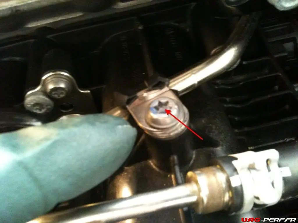
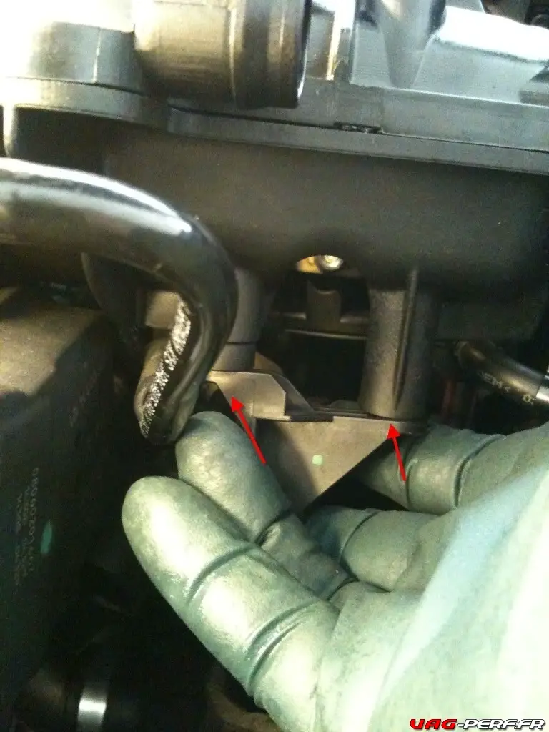
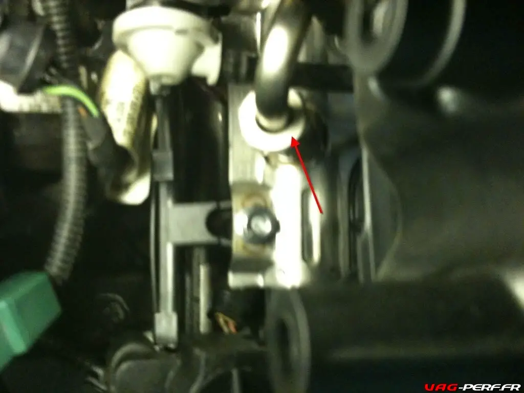
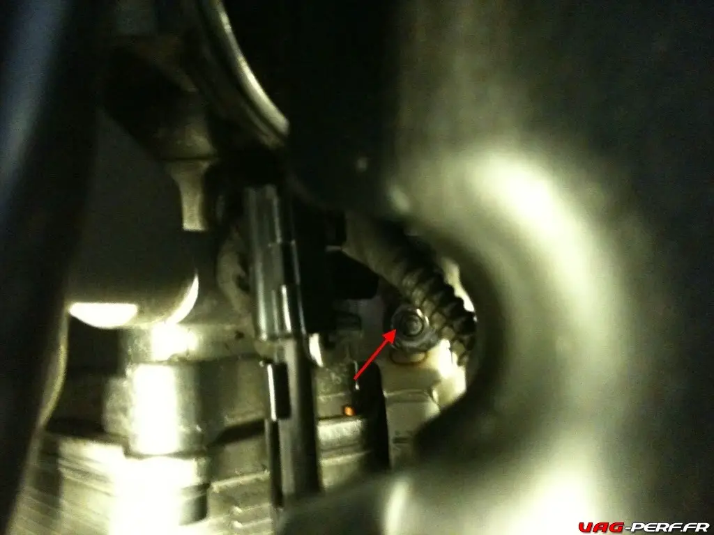
20. Remove the M10 triple square bolt for the intake manifold support bracket to the engine. This bolt is difficult to see. The location is below the intake manifold and behind the throttle body.
21. Remove the 5 upper T-30 bolts fastening the intake manifold to the cylinder head.
22. Remove the 2 additional lower T-30 bolts are accessible just above and to the left and right of the TB Module.
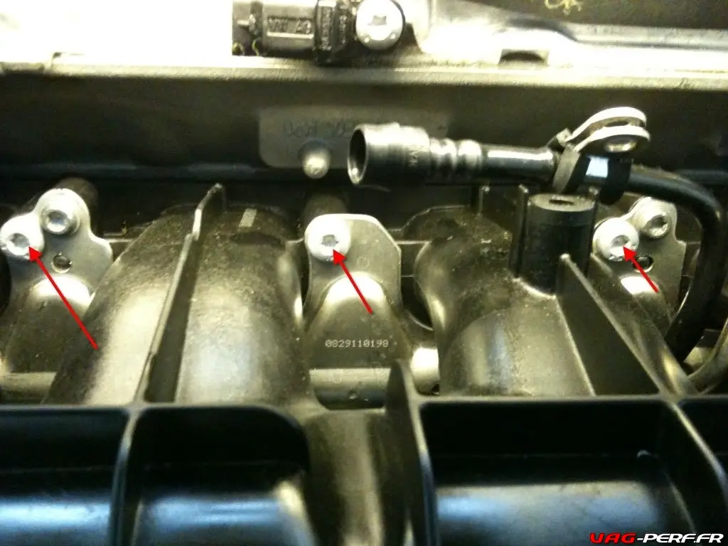
23. Remove the additional two M6 nuts located on the underside of the cylinder 1 and 4 intake runners.
24. Disconnect sensor on right side of oil filter / left side of mani; I believe this is the power source for the fuel injectors IIRC
25. Verify that all sensors are disconnected
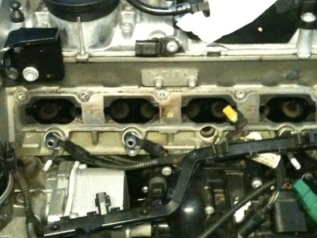
26. Verify that everything has been disconnected then gently pull up on manifold making sure fuel injectors don’t stay connected to fuel rail assembly. It’s okay if the injectors stay connected but it will most likely leak fuel onto the engine.
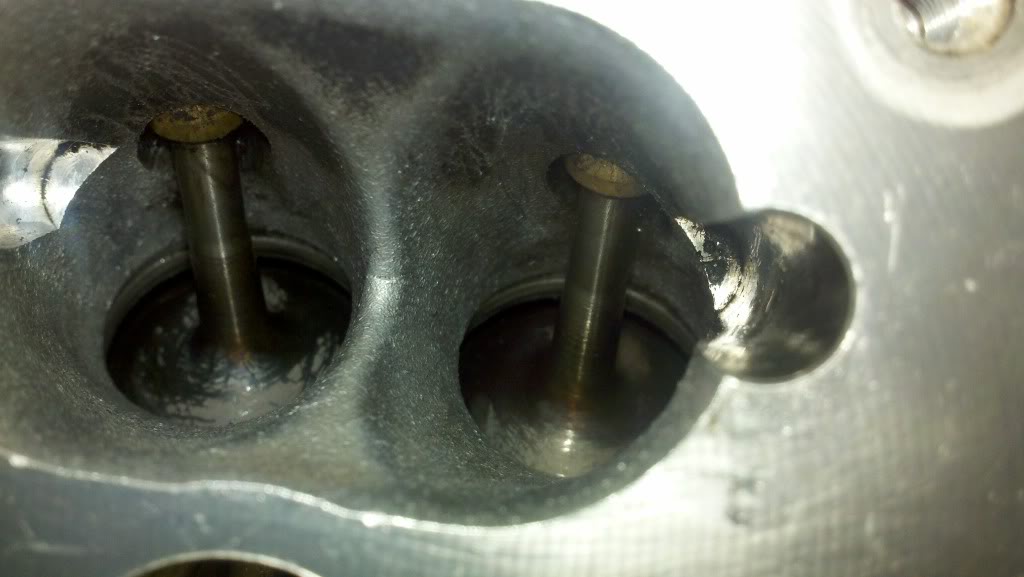
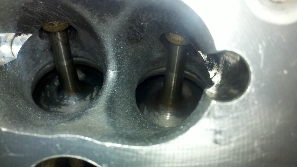
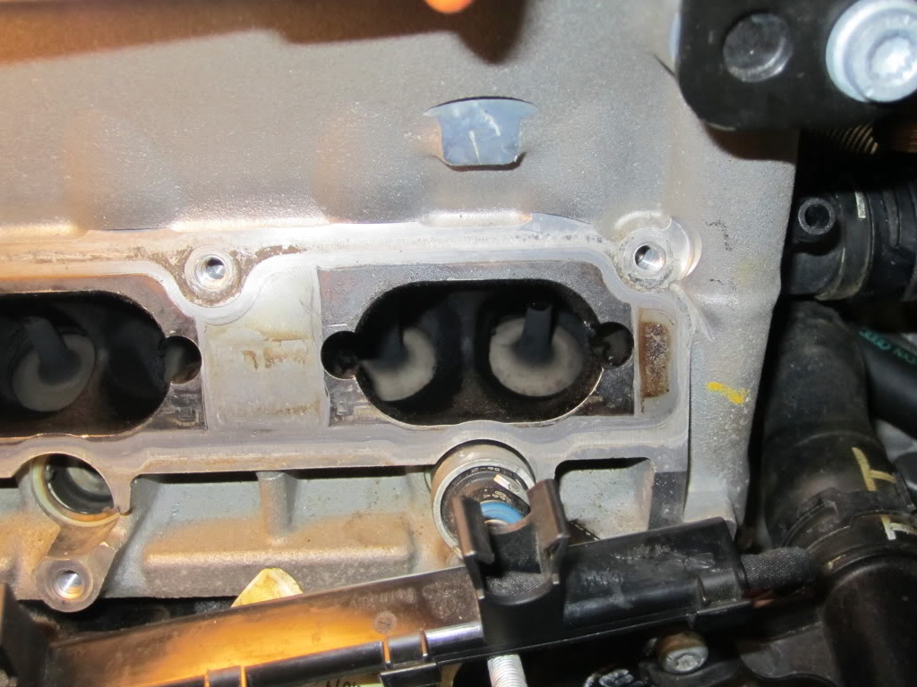
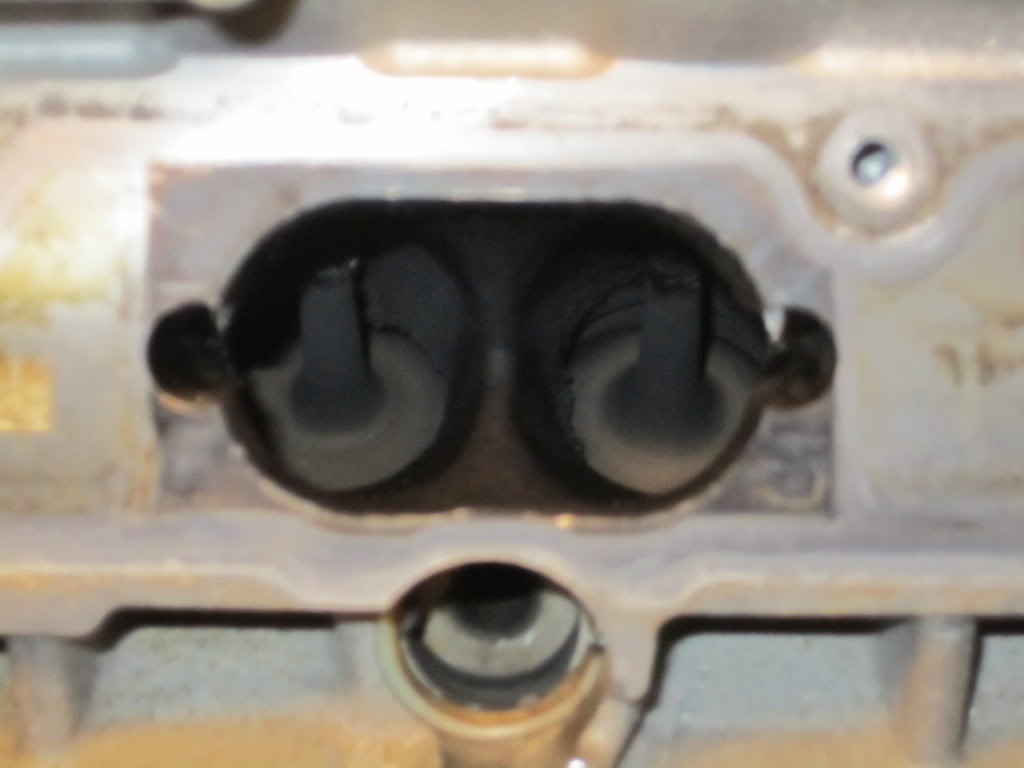
Valve Cleaning
1. Wear protective mask and gloves at all times. The GM cleaner is very strong and harmful to inhale and touch!! Use caution and common sense.
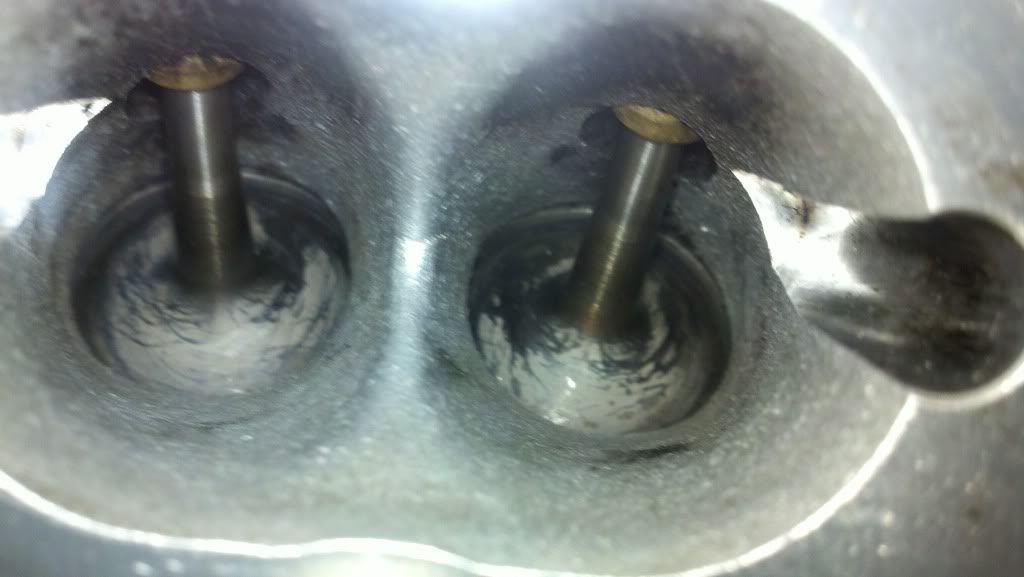
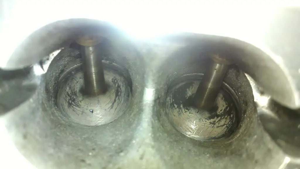
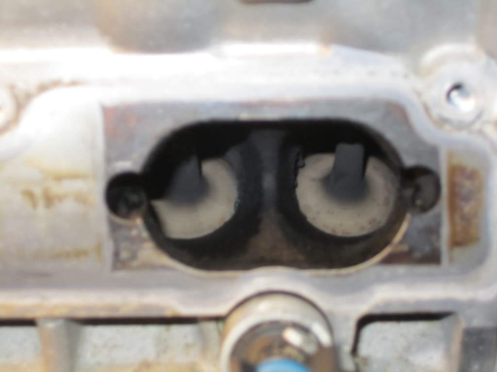
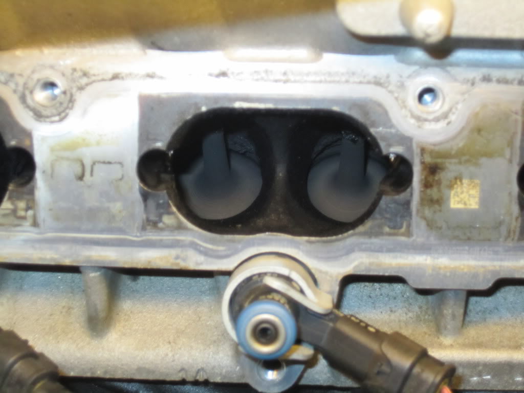
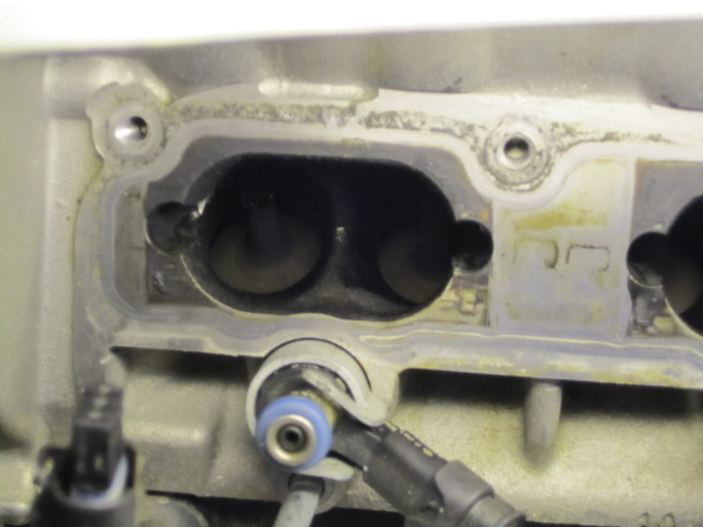
2. The GM cleaner works very, very well. It does most of the work for you. You just have to be patient mopping up the carbon soup it creates in your intake ports.
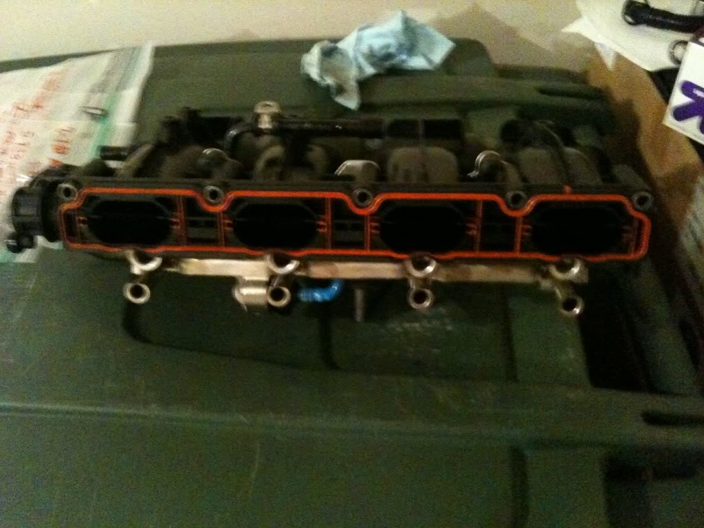
3. Remove intake flaps and soak in GM cleaner. Use wire brushes if necessary to scrape off the excessive amounts of carbon. Use rags to wipe away the carbon. Keep applying cleaner to areas that have the most build-up.
4. Hand turn the belt around alternator to turn the crank so it closes off valves on intake side. Once closed, spray GM cleaner into each valve one at a time. Let soak for 10 minutes then scrape with wire bottle brushes to loosen carbon. Tear apart 2” x 2” rags to use to soak up GM cleaner from each valve port. Use picks to move rags between the front and back of valves thoroughly cleaning all sides and “mopping” up the dirty cleaner. Keep repeating until valves are shiny silver. Use vacuum to suck out carbon bits. Use compressed air to assist with cleaning. Be careful not get bits of carbon in your eyes.
Gallerie photo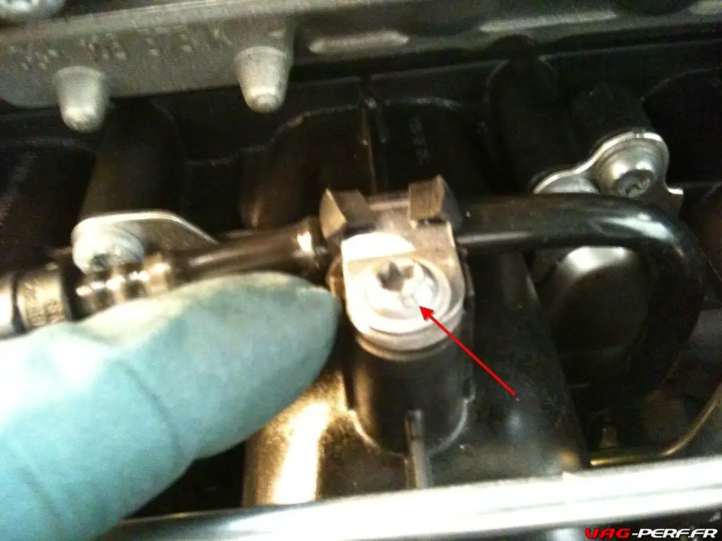


Les commentaires sont fermés